I will try to describe how the “MultiFunction” switches work – the hazard switch, the blinker switch and the ignition switch. These switches are so inter-connected and they are fairly complex in the functions they support. These are based on my 1971 240Z, but I suspect they will be similar for a wide range of Datsuns.
Our friends at Datsun really did a creative job switching all the signals necessary to get blinkers to blink and lights to light. Sadly, they also ran full current through these switches, which can lead to some problems.
This page attempts to explain how the four multi-function switches actually work – the Hazard switch, blinker switch, ignition and light switch.
Understanding the Hazard Switch
In the Fig. 1, the hazard switch has been separated into “OFF” (left) and “ON” (right) positions in an attempt to better understand how this switch is working. Since the switch spends most of it’s time “OFF”, let’s start there. The words that are in light grey font are ‘not connected’ for that particular switch position.
Hazard Switch OFF (Fig. 1, left side)
- Terminals 4 and 5 are connected. This takes 12V from the fuse box into Terminal 4 and routes it to power the blinker flasher via Terminal 5. (The blinker flasher is then wired to the blinker switch on the steering column)
- Terminals 6 and 7 are connected. This takes 12V from the fuse box into terminal 6 and routes it to power out terminal 7 the “stop switch” at the brake pedal. (The stop switch is then also wired to the blinker switch on the steering column)
- The remaining contacts are “open” – that is, they are disconnected from anything else in the hazard switch.


Hazard Switch ON (Fig. 1, right side)
- Terminals 4, 5, 6 and 7 are now ‘open’ – there is no power provided to the blinker flasher nor to the “stop switch”. There are no brake lights or blinker when the hazards are on.
- Terminals 1, 2, 3 8 and 9 are all connected together into a single circuit. Terminals 2 and 3 are the front blinkers, terminals 8 and 9 are the rear turn signal/brake lights. Terminal 1 supplies the flashing voltage from the hazard flasher relay. The hazard flasher relay is powered 100% of the time from the same 12V that feeds terminal 6 (stop lights).
Fuses for brakes and hazard (1971 240Z)
Flasher (blinker flasher) fuse connects to Hazard Switch Terminal 4Stop fuse connects to Hazard Switch Terminal 6. It also powers the Hazard Flasher relay.
Diagnosis
As a general rule, if ALL lights are affected, the the problem is ‘in front’ of the hazard switch. That is, all the wiring, fuses and connections leading up to the switch, including the switch itself.
If only some of the lights are affected, then the issue is likely between the switch and the bulb, including all bulbs, sockets, connectors, wiring and the switch itself. This is highly simplified – it is made more complex by the interplay of the different multifunction switches.
Good troubleshooting always starts with “do you have it plugged in?” and “ïs it turned on?”
That is to say, “do you have power?”
- Remove the fuse cover
- Visually inspect the FLASHER and STOP fuses
- If the fuse if visibly blown, replace it. Do not replace with a larger amperage value to avoid ‘popping’ the fuse again.
- Test the voltage at left side of both fuses. This is the voltage ‘source’ side.
FLASHER fuse should have 12V on the left side when the ignition switch is in RUN (not in START and not in ACCESSORY).
STOP fuse should have ‘full time’ 12V on the left side, straight from the battery. - Measure the voltage at the right side of both fuses and confirm 12V
- Are all 4 flashers working?
- None are working
- Suspect emergency flasher relay
- Suspect wiring to hazard switch
- Suspect hazard switch
- Only some are working
- Suspect failed bulb(s)
- Suspect corroded/dirty bulb socket
- Wiring issue from – and including – the hazard switch to the lights. A failure ‘before’ the hazard switch would affect all lights equally
- None are working
- Are the brake lights working?
- None are working
- Suspect “Stop Switch”
- Only one side is working
- Suspect failed bulb
- Suspect corroded/dirty bulb socket
- None are working
Understanding the steering column multifunction switches
Breaking down the switches into simpler parts
The gallery of images below walks you through ‘dissecting’ the switches into simpler ‘sub-assemblies’. Once we have ‘logically disassembled’ the switches, I will discuss how they work, one-by-one. I started by redrawing the schematic from the ’71 FSM. Then I will ‘take apart’ each switch – first the lights/wiper/washer switches, then the blinker, hi/lo beam switches.

1. Multifunction switch illustration from FSM wiring diagram (’71)
Since I don’t know what’s what at the motor end, I can’t really explain what’s going on here, exactly. Something looks odd on my FSM wiring diagram, so this is my best guess until I can do some more research.
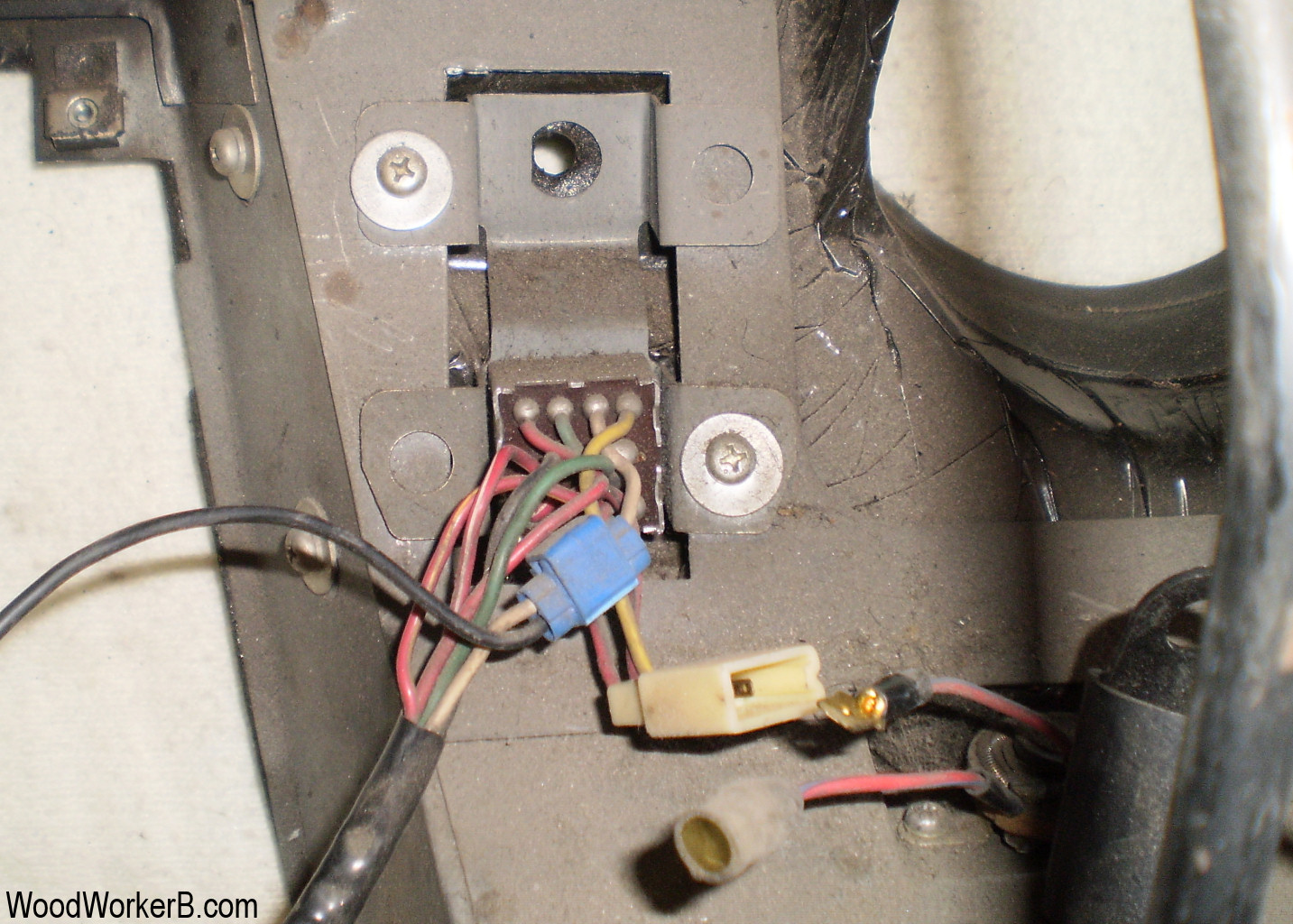
Photos of the switches

Blinker (right foreground) and hi/low beam switch (left background). Just above and left of the center of the image is a flat copper ‘spring’ (connected to blue wire). This is for the windshield squirter.
Other Resources
Some Electrical Basics and Troubleshooting – good info on tracking down voltage drains
Understanding the turn signal switch
Go to the Blinker Switch page.
Understanding the lights, high beam & low beam
This function is part of both switches – the knob that turns on the running lights and headlights combined with the high-low dimmer switch (pull-push of the blinker lever).
Lights Off

Running Lights

Headlights on

Red: 12 volts from the fusebox is routed to all four side markers, tail lights and front running lights (same as above).
Green: Ground is routed to the Hi/Low switch on the blinker assembly. This switch alternates between pin 15 and pin 16 (see Figures 3 and 4), high beam and low beam. Which-is-which is not clear from the FSM wiring diagram
Fig. Y – Headlights ON, Dimmer position 1
Fig. Z – Headlights ON, Dimmer position 2